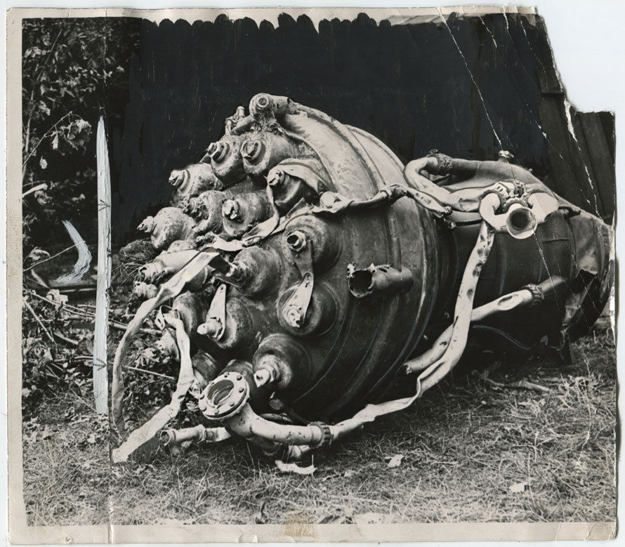
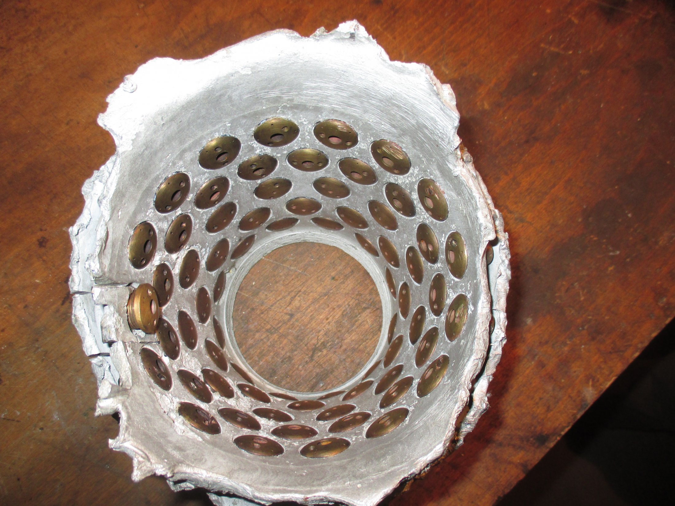
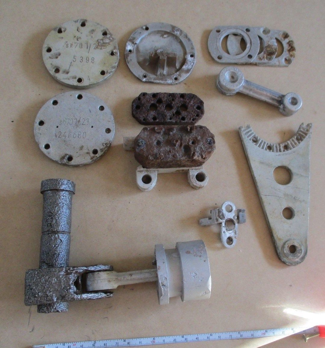
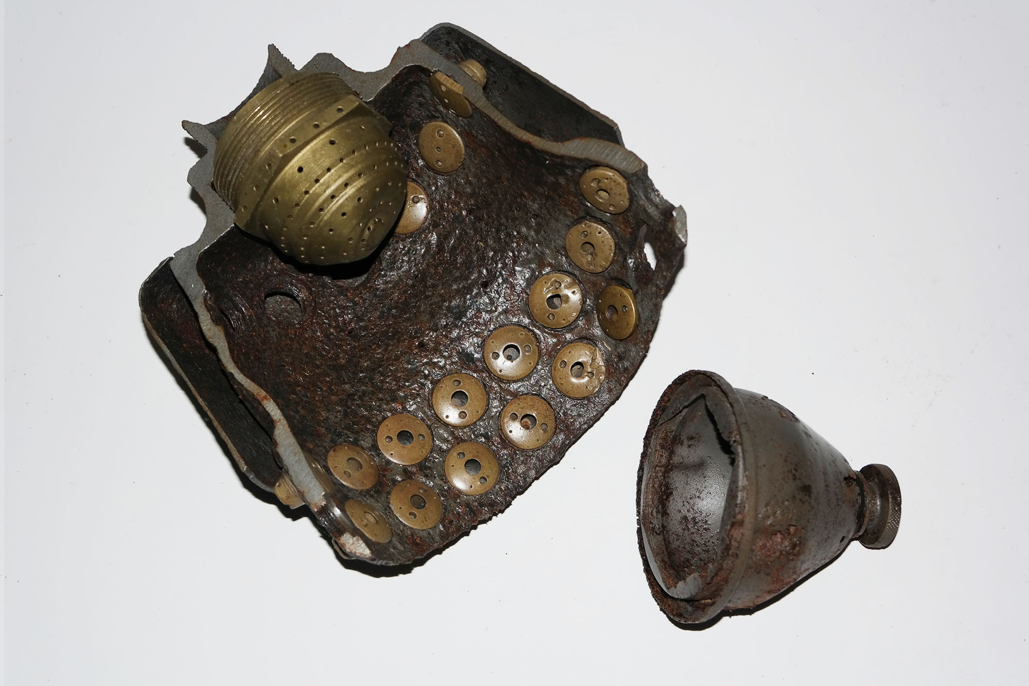
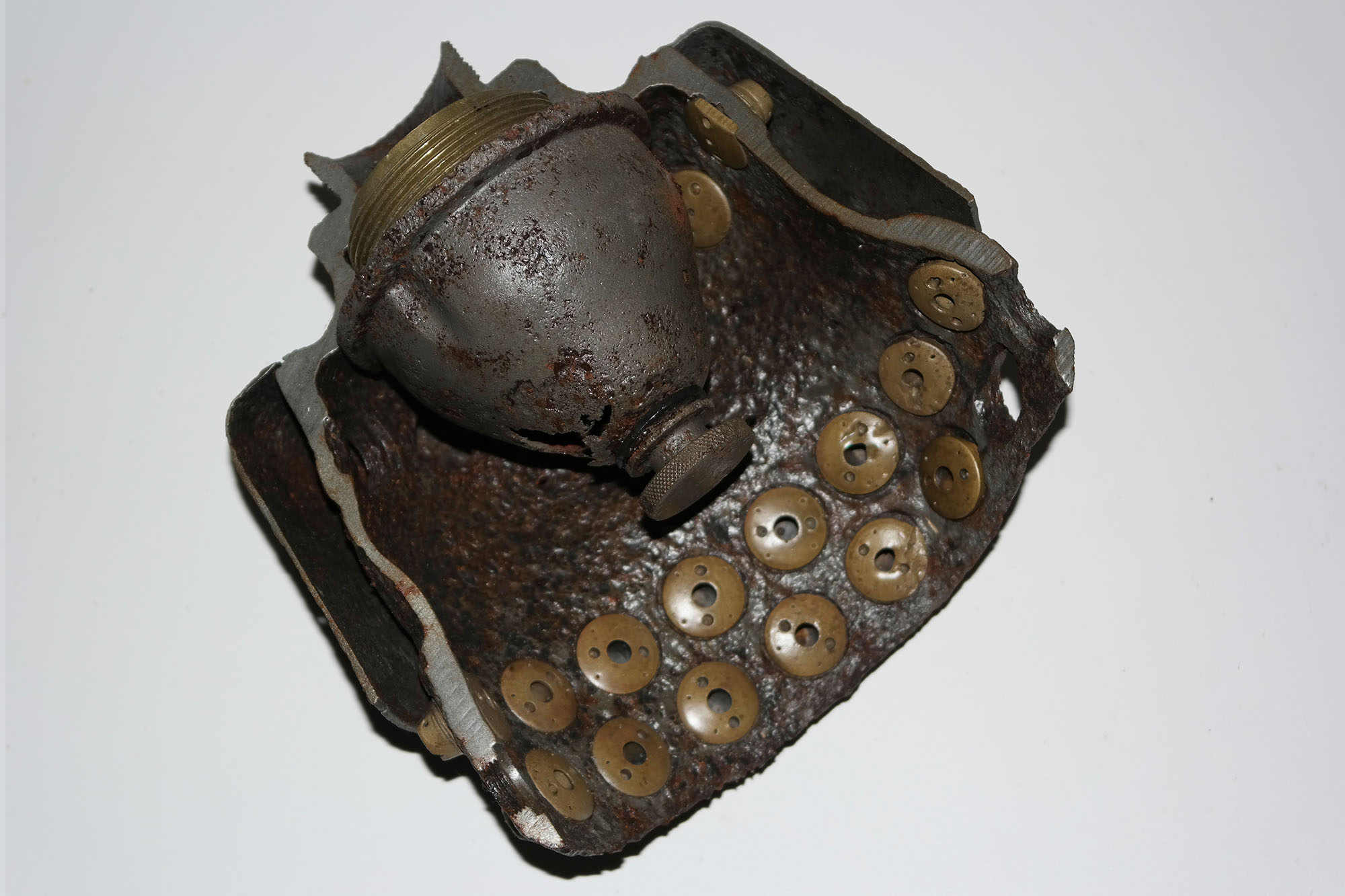
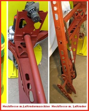
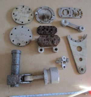
About ten years ago now I was shown a relic, found in the sandy soil of the Peenemünde woods, that turned out to be part of a simple system for evaluating the fuel injector inserts used in the 25-ton test engines of the A4/V2 missile project. At the time the rusty piece didn’t hold my attention for long, but the main feature that stuck in my mind was its sheer simplicity. It was a short piece of steel pipe, perhaps 150mm long and 25mm diameter, and quite rusted. At one end of the pipe was a fragment of brass that may have been the remains of a valve of some kind. At the opposite end of the pipe, there was a hole – about the size of my thumbnail – with a thread much too fine to be for a standard water connection.
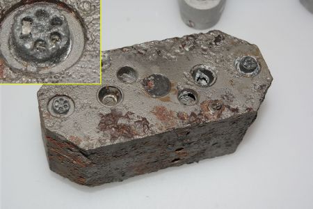
What this thread was used for was beyond dispute, because still fitted to this end of the pipe, when found, was a standard brass fuel injector insert. The threaded tube was part of a test rig – and significantly, it was used to test just one injector insert at a time. At some point the finder of this relic had removed the injector, mangling it in the process. It was a while ago, but once removed, if I recall, it was nothing out of the ordinary – a typical D or E echelon A4 fuel injector made anywhere between 1942 and 1945 (looking much like a type 3305D). See my previous post for details of injector types.
Below: 3D models of type 3304 D and 2131 E inserts. Modern 3D modelling provides us with the perfect way to visualise the design of the injector inserts and Alexander Savochkin’s models, accurate in every detail and faithful to the original HAP drawings, allow the viewer to explore the injector cavity and see every connected orifice. Use mouse/finger to move the injector and the mouse roller will allow you to zoom in – even inside the injector!
Injector insert 3304 D with central stream Copyright Alexander Savochkin
Fast forward a few years to when I wanted to try to test some V2 injector inserts to discover their relative flow rates and observe the different spray patterns produced, and I recalled the simplicity of the rusty pipe I had seen in Peenemünde. I also wanted to try to photograph and video the inserts in action – to dispel some of the mystery of the functioning of the fuel injectors, locked away as they are in the dark secret vault of the V2 rocket’s injector head. And I hoped I might be able to do the same simple thing the German technicians had done 75 years ago – and perhaps even use an everyday mains water supply to do it.
I think it likely that the Germans used a water tank on a tower or a high roof. There are some tower structures, and roof tanks visible on RAF reconnaissance photographs of the development works in Peenemünde, and their purpose is still not fully understood in all cases.
But could a water tank 15 to 20m high on a roof or tower, or even just a regular mains supply, typically 2 to 3 bar (or 30 to 45 psi), really provide a volume of fluid at a pressure consistent with that supplied by the V2’s powerful steam turbine driven pumps?
The answer, perhaps surprisingly, is yes. The pressure and flow rate provided by the turbo-pump is of course very high; it had to be, it was pushing over 120kg of propellant (fuel and liquid oxygen) per second through nearly four thousand small injector orifices. But if we isolate just one fuel injector, and analyse its solitary pressure and flow requirements, we find that even a typical good domestic mains water supply can be used to mimic the performance of the turbo-pump quite comfortably, with pressure to spare. And this is more or less what the German researchers did, in the early days of the 1940s, to evaluate the relative performance of a large number of sample injector inserts having a wide range of orifice and cavity designs.
The various injector permutations were subjected to numerous tests, and of course, the single insert test to record comparative spray shape and flow data was only one of many performed at various military and academic research groups in Germany.
At first glance, the single injector test method does seem to be a very poor analogue for the real process on almost every front. But variations in fluid viscosity or the variable pressure of the turbo-pump feed system just meant that the values had to be corrected for these factors when the data was used as the basis to evaluate actual propellant flow performance.
The advantage of this test method was its speed and operational simplicity – it had the absolute minimum number of variables as only one important factor required proper management: that being the residual pressure of the fluid behind the injector. It was however essential that the pressure was the same for all specimens so that the flow rates could be assessed proportionally. That the flow rate from the injectors might be different when running ethanol and water through the inserts was merely a matter of correcting the numbers with a suitable viscosity coefficient.
So, how to replicate the device found in the woods?
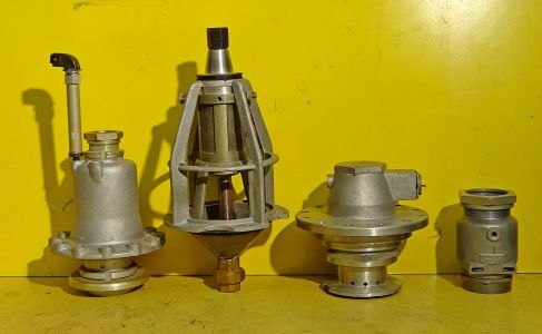
First, I needed to test the general viability of the idea. And after an hour on the lathe, and the addition of a copper pipe fitting or two, I was able to attach a 75-year-old V2 injector insert to the mains water supply in the workshop washroom. It worked well, too well, I managed to get myself, and everything else within a five-meter radius, utterly soaked (even the ceiling was dripping). The tests revealed I would need some method of stabilising and reducing the mains water pressure as well as some way of measuring the water pressure behind the injector insert to a reasonable degree of consistency – if not high accuracy. For this type of test accuracy in an absolute sense is not critical – but being able to produce a precise and repeatable water pressure for each test is vital. A widely available domestic central heating system pressure regulator with a gauge on the outlet side would do the job – and at minimum cost – NASA we are not.

A few practices with the test rig (outdoors and wearing waterproof clothing!) established that a steady water pressure of 2 bar at the insert would be more than sufficient to initiate the nebulising and streaming function of the injectors. The injectors seemed to start functioning correctly at residual pressures of anything over 0.7 bar. By ‘correctly’ I mean producing streams and hollow cones of fine droplets with minimal congestion and ‘dribbling’ from the injector face. But a higher setting of 2 bar also provided volume flows in one minute that looked roughly consistent with the expected average of 3.3 litres per minute (LPM) per injector that my rough calculations had suggested would be needed. This rough estimate, what my old physics teacher, Barry Swain, liked to call a ‘Wild Woodbine’ – not for its sweet fragrance but because it might be doodled on the back of a cigarette packet (a napkin is just as accurate if you’re a US reader) – runs something like this: 5200 litres of fuel, minus say 21% for tankage, cooling use, and burn time over 60 seconds, divided by 18 (the number of burner cups on the V2 engine), divided by 68 (the number of orifices per burner cup) = 3.35 litres).

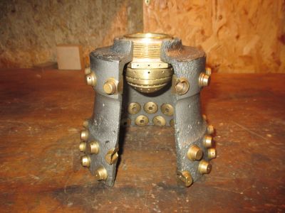
Before testing, some preparation was required. Samples of three of the standard injectors, 3304D, 3305D, and 2131E were selected from our collection and cleaned, making sure that all apertures were clear. Some of these inserts may have spent decades in the ground, and all were nearly 75 years old; a good wash and brush up was essential! A new injector was also created on the lathe to mimic one of the twenty-four 2mm feed holes that were drilled into the burner cup wall at cup rows B and C. This was so that a simple drilled feed hole could also be tested for flow rate and jet pattern along with the more sophisticated brass inserts. The ‘drilled hole’ version was made to fit the same nose thread used for the brass inserts. The 2mm diameter orifice was directly drilled through a 4mm thick base (consistent with the 4 to 5mm wall thickness of the burner cups in the vicinity of rows B and C). But unlike the brass inserts, there was no swirl-cavity or anything else behind the drilled orifice.

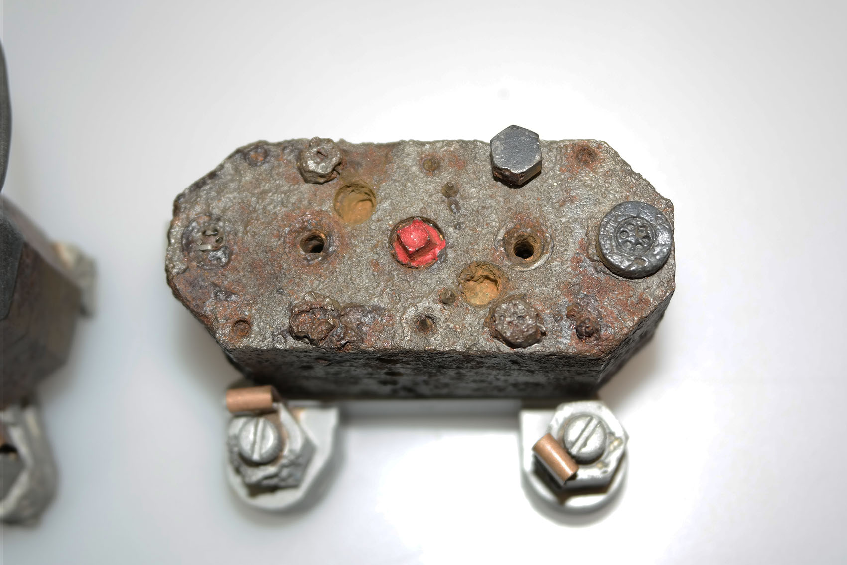
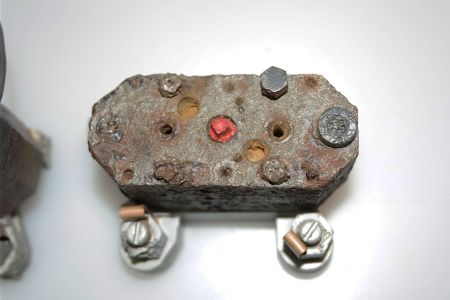
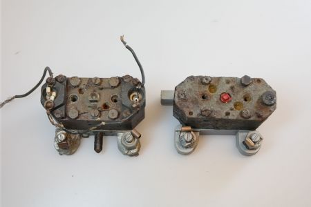
A high vacuum grease was carefully applied to each of the insert’s threads to help form a temporary pressure seal with the nose-piece of the test rig. Rather than test and photograph each nozzle at only the chosen 2 bar water pressure – I also decided to test the flow rate and nebular/stream pattern for each insert at a low water pressure value as well. I chose the pressure value for this by comparing the point at which each injector insert just began to function correctly – that is to say when a nebular of spray droplets formed and the streams were steady. The pressure value for this point was approximately 0.3 bar and consistent for all inserts. Unfortunately, the pressure gauge fitted to the rig was neither accurate nor particularly stable at residual pressures lower than 0.5 bar! The needle position responded sluggishly to changes in tap setting and refused to settle in the range of 0.2 to 0.4 bar so that I am unable to state with any certainty exactly what the value was for this practical start point. However, the setting was as consistent as possible and what is clear is that the flow rate at this setting is far too low to have allowed the engine to function – so it has the minimal utility of merely marking the lower limit of flow for each insert tested (Note: the red indicator on the gauge is not connected to the mechanism and is not used in the tests).
From here on the test procedure was straightforward. Each insert was tested at the low-pressure point (as defined above, but described for brevity on the photos as <0.3 bar and as 0.2 to 0.4 bar on the results chart) and at the higher 2 bar residual pressure setting. Each test was photographed to compare the spray pattern for each insert at both pressure setting. The water flow from each nozzle tested was captured in a vessel for one minute, and the volume measured and recorded (see chart below).

The results offer little in the way of surprises as regards the flow volume passed by each injector insert. However, the comparative shape and limited nebulosity of most of the spray patterns will, I think, surprise some. A practical test like this, though limited in its scope, does throw some light on this rarely visualised phenomena. It’s worth pointing out that existing literature on the subject has tended to be dominated by somewhat theoretical descriptions of the spray profile of V2 fuel injectors. It is a fact that very few commentators have ever seen V2 engine propellent injectors in action.

My tests were limited to water rather than ethyl alcohol and water (mixed 3 to 1) that the injectors were designed to use. And although the fuel would have produced a finer mist of spray droplets (ethanol shears and atomises in a way similar to water but vapourises much quicker) the spray patterns seen strike one as somewhat crude and thick streams of alcohol fuel, would I’m sure still have been in evidence with the higher volume 3304D injector and 2mm plain hole. These inserts show virtually no dispersion of the central jet at 300mm from the injector face (see pictures above and below). We know that one of the chief concerns of the Kummersdorf/Peenemünde combustion team led by Dr Walter Thiel, was achieving full vapourisation of the alcohol (the liquid oxygen vapourised readily with minimal injector design effort) and that complete success in this area had still not been realised by the end of the war. When we reflect on the confined space within the injector cup, and the splashing and spattering these coarser fluid streams must have occasioned, it is difficult to picture how this can have prevented large, cool (taking longer to vaporise) drops of fuel raining down, at least part way, through the central axis of the combustion chamber. With negative consequences for uneven molecular level mixing and the consequently reduced combustion performance caused by zones too rich in fuel.

The steeply compromised nature of the injector head, designed entirely to facilitate development, becomes increasingly clear to everyone involved after mid-1943. The restricted burner cup design, with its plethora of screw-in injector inserts – so useful when trying out new ideas on the test stands but such a liability when trying to streamline for production, limited the possibilities that Thiel’s combustion team could employ to improve performance without a radical redesign of the injector system. The use of higher flow, but less efficiently atomising nozzles and orifices became an essential compromise that had to be made in the broader interests of making the V2 missile available quickly for the war effort. There just wasn’t the room in the head cups for more efficient injectors – and neither did they have the luxury of time to develop the underlying technology of the injector head in a way that by then Thiel’s team knew was essential.
The design and development of the fuel injection and diffusion technology at the army research stations, and elsewhere, was almost entirely empirical. At the start, the research was steered fruitfully if briefly by contributions from experts from industry. But the limited correspondence of existing technical knowledge of atomisation to something so novel as rocket work was soon exhausted. Thiel and one or two close members of his team made great strides and gained much detailed understanding of how the fuel spray shears into evaporating droplets, and how a chemical reaction takes place in the gas phase and how the hot gas breaks the remaining liquid into smaller droplets, which mix, evaporate and burn. But despite the clear technical breakthroughs and the mass of data the seemingly endless tests produced, his team failed to develop a coherent theory of how it could all be systematised and more importantly, simplified.
A fully ramified and accurate theory regarding injector design and combustion phenomena was decades away from formulation in the era of the V2. Indeed nothing approaching a practical and comprehensive injector/combustion cookbook could be claimed until at least the middle years of the 1960s.
Walter Thiel, Germany’s and at the time, the world’s top rocket combustion expert, was killed with his young family in the RAF air raid of August 1943, and no further progress was made with the development of the V2 injector system until well after the end of the war.

Observations
The chart above shows the results of the water tests on samples of three historical inserts plus the new drilled hole insert. The bar chart is mostly self-explanatory, but the additional bars in grey show the estimated 8% increase in volume expected once the data is corrected for viscosity and pressure variations from the turbo-pump. Of minor note is the fact that the higher flow 3304D insert, with its additional thick central stream, delivers over 13% more fuel than the 3305D. More significantly, if the injector insert permutations are combined with this data, it can be readily shown that less than 60% of the fuel delivered to the combustion space by the V2’s injector head was in the form of an atomised or nebulising spray. If the contribution of the four cooling pores employed on inserts 3303D, 3304D, and 3305D are also taken into account, then the atomised component falls to nearer 50%.
Speaking personally, this is somewhat at odds with my previous, mostly abstract understanding of the V2’s injector function. I think the picture I had developed in my mind, in the absence of any compelling graphic evidence to contradict it, was of a burner cup ejecting a dense fast-moving nebular column with a more or less fully atomised structure. And I think it is very likely that others will have drifted into forming more or less the same distorted image owing to the general lack of compelling imagery. A more accurate picture seems to be that of a somewhat ‘lumpy’ injector head performance that delivered about half of the fuel to the combustion space in the form of deflected streams and large droplets and it does seem likely that efficient atomisation across the combustion plane was much less dominant in the vapourisation process of the V2’s engine than is often assumed.
In the end, the insert test imagery only confirms the undeveloped and embryonic nature of the injector technology of the V2 thrust chamber. And to be sure, the chaotic mix of dense nebular, fine drizzle, and heavy rain of larger droplets that emanated from the burner cup may, in its tumult, defy precise description – the one thing we can say for sure is that it worked well enough.
The principal reason for these tests was to evaluate the relative flow characteristics of the fuel inserts and to visualise them in action.
Notes on the apparatus: The pressure regulator limited the static pressure of the test system to 2.5 bar – this figure was checked at the beginning and the end of the test sequence. An FM Mattsson self-draining compression tap regulated the actual test pressures, and the value was set by eye using a gauge registering the residual pressure when the injector was under test. The static pressure of the water supply without the inline regulator was just over 3 bar.
Further reading:
Rocket Missile Propulsion, 1958, North American Aviation
The History of Liquid Propellant Rocket Engines, 2006, George P. Sutton
Rockets and Missiles, 1955, G. Sutton
The image gallery below has all the above pictures in higher resolution, some with additional text, as well as additional pictures not included in the article.