With a few notes on the development history of this critically important technology
The time boundaries for the development of the fuel injection system of the A4/V2 25-ton thrust engine are simple enough to state; the process began at the Kummersdorf army proving grounds in September 1937 and the pattern of inserts was finalised for production in Peenemünde almost precisely four years later in September 1941. But confined within this period is a vast amount of activity – involving the effort of a large number of unrecognised people working in commercial operations and academic institutions across Germany.

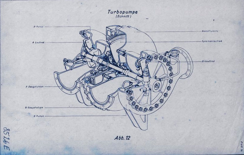
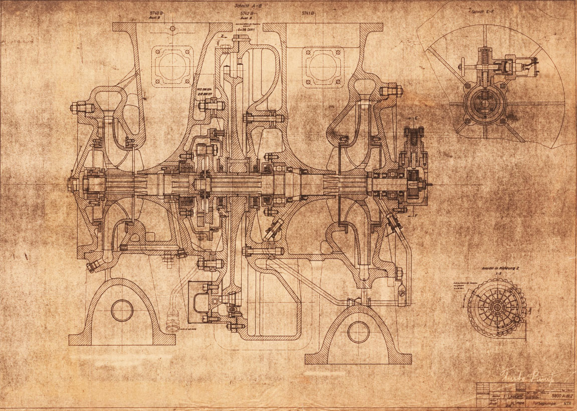
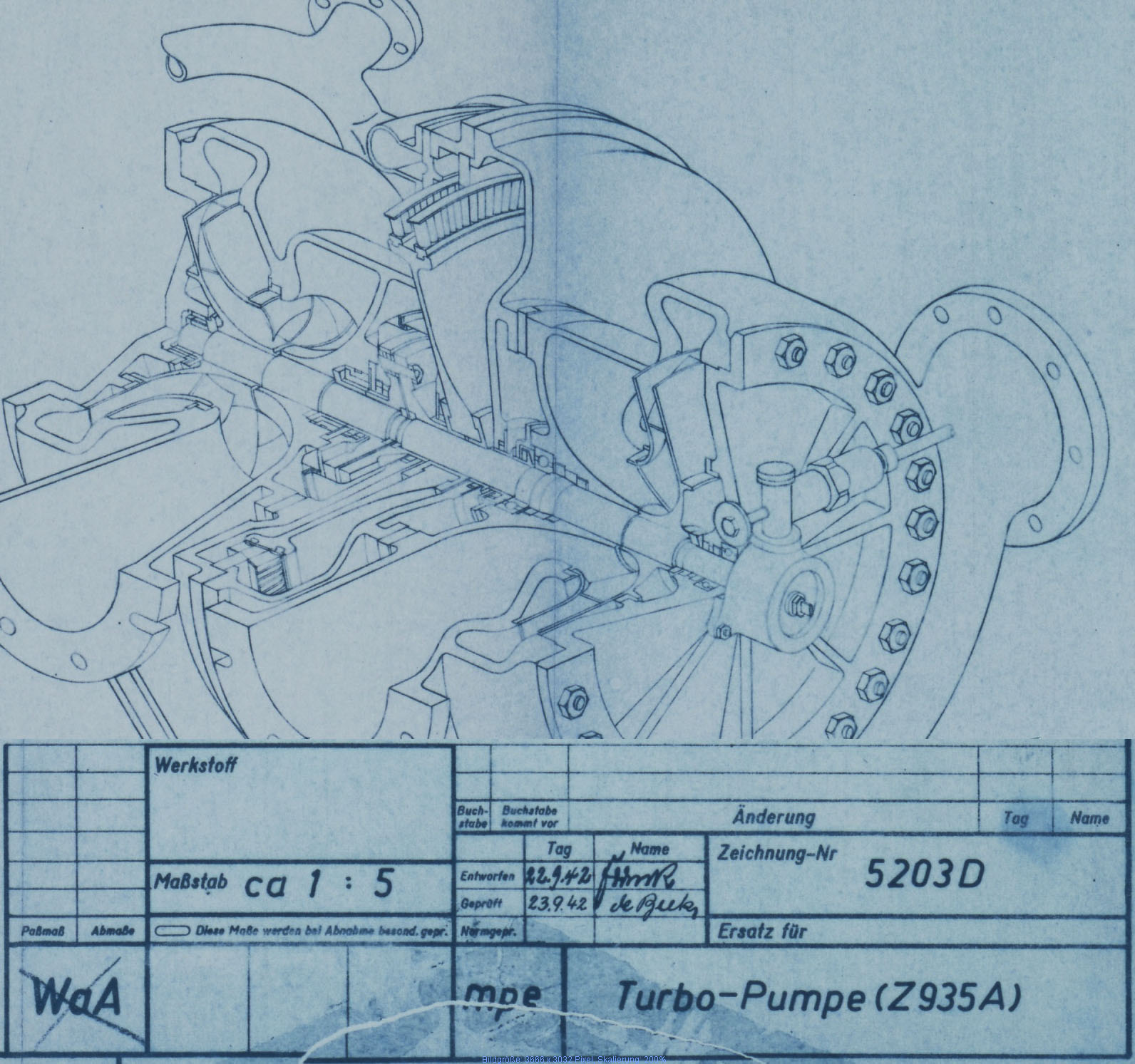
In this regard, the role of commercial contractors in the development of the first ballistic missile often receives scant coverage as a source of progress and innovation. But from the earliest days of German army rocket research, some leading technicians had recalled the valuable contribution made by commercial operations like Kreiselgerate (Gyro Devices) Siemens, and Askania amongst others. With one or two even going as far as to cite the crucial role of companies like the turbo-pump developer, Klein, Schanzlin & Becker (KSB) AG, of Frankenthal, as epitomising the potential for fruitful relations between a commercial organisation with specialist expertise and the military research stations.

One company that made just such a significant contribution to the V2 story was Gustav Schlick GmbH of Dresden. Established in 1902, the Schlick company had long-established expertise in the field of spray technology and fluid atomisation. They had no experience with rocket motors, hardly anybody did but were able to generalise their knowledge and expertise for the needs of the German army missile program. By 1937 the Schlick company was collaborating on the design of injectors and manufacturing finished nebuliser inserts for testing by the Kummordorf combustion team headed by Dr Walter Thiel.
The ‘swirl’ or gyroscopic fuel injector
As a result of this military and commercial collaboration, the swirl or ‘gyroscopic’ injector nozzle was patented in Germany in 1938 in a patent document titled simply ‘Rakete’ (or Rocket). Dr Walter Thiel of Kummersdorf was identified on the proposal along with Dr Walter Dornberger of Berlin Charlottenburg, and no reference was made in the patent to indicate that the origin of the new nebuliser was the achievement of a military facility (Kummersdorf). The patent describes the design of new ‘Centrifugal force nebulisers’ that successfully shear or atomise the liquid fuel for a rocket engine into tiny droplets and increase combustion chamber performance by 30% compared to existing ‘blast nozzles’ [2].

The claim that rocket thrust performance was boosted to such a degree by a swirl action of the injector does not appear to be born out by the test data – indeed many swirl type nozzles were removed from later A4 injection chambers with little or no detectable deterioration in performance. But this would hardly be the last armament patent that routinely overclaimed performance. Once a critical minimum number of injectors of a particular flow volume and aerosol form had been achieved the primary performance test methods available to the combustion specialists of the era (jet velocity and chamber pressure) were of insufficient resolution to discriminate accurately between small, but dimensionally noticeable, permutational changes. That is, typically they were able to measure the difference between say 40 jet orifices and 45 but not 70 and 75. This resolution problem is partly why the knowledge gained developing the 18-pot burner system did not provide a knowledge base to build a simpler and more efficient injector system during the war. Significant progress in this area as a result of more precise test evidence-based injector modelling was achieved only after 1946 [3].

The ingredients come together in one pot
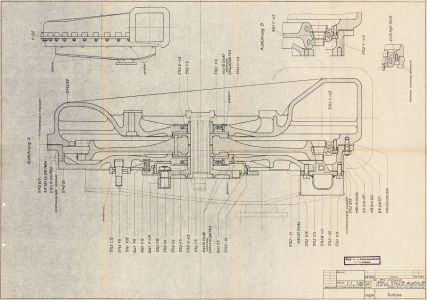
The Einheitskopf (unit head) injector of the type 4B engine, from 1938/9, showed many of the critical elements that would be used in the 25-ton A4 motor a few years later.
The photo below shows the result of an explosion in a 4B engine. Discovered in a scrap pile in Peenemüde a few years ago, the fragment of injector head probably originates from tests in Kummersdorf in c.1938. The motor fragment shows threaded sections for LOX and fuel injector inserts in similar proximities and relationships to those seen in the individual burner cups of the later A4 engines. The relic also features plain borings for regenerative fuel cooling and drilled passageways for the supply of fuel to the combustion cavity – again vital elements of the successful 25-Ton engine of 1942. Collaboration with the Schlick company seems to fade from the record after 1939 – and it is probably fair to say that by this time Walter Thiel’s combustion work group had assimilated the company’s relevant knowledge and had progressed well beyond anything Schlick may have been able to contribute to the field of fuel injection.

The sound logic of the screw fit injector insert system
To develop an injector head that was efficient in function and simple to manufacture, was always on the table when planning engine development at Kummersdorf and Peenemünde. However, the developmental convenience of a system where a wide range of orifice and injector cavities could be swapped around quickly, via threaded inserts, and be tested with the minimum of downtime, allowed a large number of tests to be performed. And thus a substantial body of empirical data to be developed in the shortest possible time. Later on, the combustion specialists assumed, this body of data and experience would provide them with the broad understanding needed to simplify the propellant injection process and the engineering hardware required to deliver it. This assumption turned out to be critically flawed.
 injector pot")
The small inserts themselves were easy to manufacture, with the basic shape formed on lathes, with further operations to form central cavities and additional apertures also made on lathes but more typically, later on, drill presses or milling machines.

Although simple to make, the sheer number of inserts used in trials of the 25-ton engines did place significant demands on skilled labour (some 18-pot trial engines used as many as 1224 machined copper alloy inserts!). But overall the general insert concept was sound and allowed for experiments that could employ a wide range of flow volume and nebulising permutations with no structural changes to the design of the injector head itself – already a very complex and challenging component to manufacture.
The fact that this injector design led to production difficulties later on and contributed to a lack of flexibility that hampered the search for a better injector solution could not reasonably be foreseen or preempted by the development team in the earliest years of the 1940s – struggling as they were with the basic functionality of new technology.

Static burner tests performed with the range of workhorse 1 to 1.5-ton engines, developed primarily at Kummusdorf, showed early on that the variation in temperature, measured from top to bottom of the injector cup was significant. And the highest temperatures found in the lower surfaces of the injector head could easily imperil the survival of the lower echelon injector inserts (rows C, D, and E) raising as it did well beyond 700° Celsius before the end of a burn. The copper alloy inserts would begin to distort at around 600°c, and the seating face of the insert could slump away from the injector wall leaving gaps, and even fail entirely at temperatures exceeding 800°c. The solution was to provide four small cooling pores in the face of all lower echelon injector inserts.

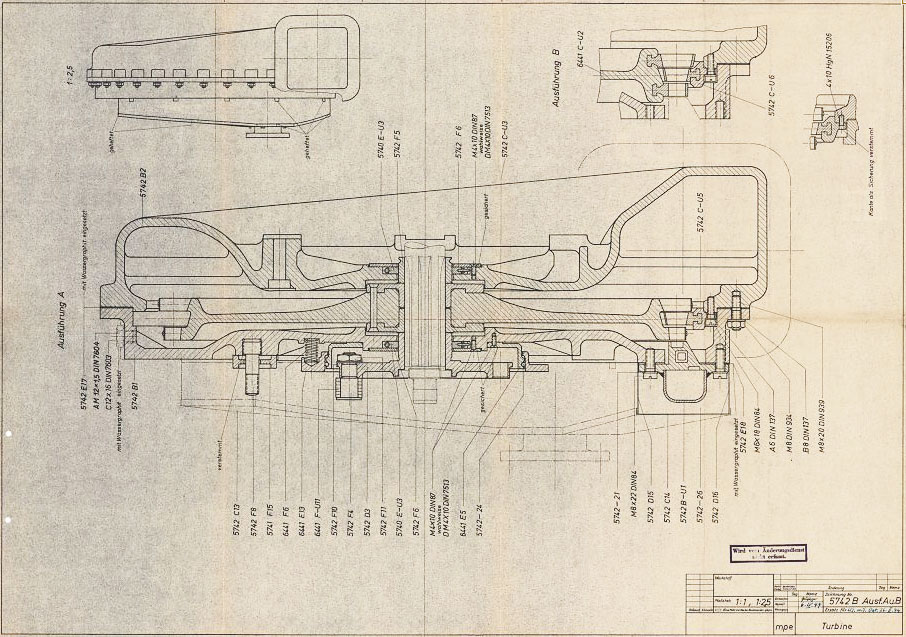
Later in the cooling pores would be restricted to the inserts positioned in lowermost rows D and E. The remaining first row of inserts placed at row A, adjacent to the liquid oxygen (LOX) spray head, did not require additional cooling. The temperature in this location was lower due to the cryogenic cooling effect of the LOX, as well as the high volumes of coolant/fuel circulating immediately adjacent to this area. By 1942 the Peenemüde combustion group had settled the fuel injector insert designs and the pattern of distribution within each burner cup, and these factors were not significantly revised until well after the war. When they came, these improvements were again made in Peenemünde and mostly by German technicians but under the control of the Soviet Union [1].
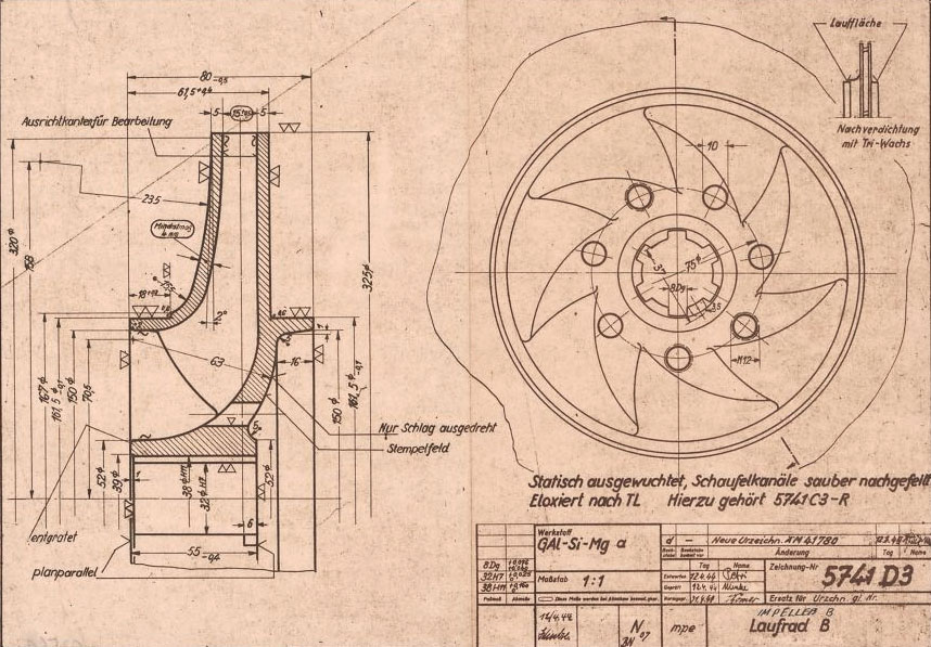
Early development versions of the nineteen and eighteen pot head were made of aluminium.

The photo of the aluminium burner cup above shows 68 machined copper alloy injector inserts. Later this number was reduced to just three rows totaling 44 inserts with an additional 24 drilled orifices (usually described as feed holes) created by simply drilling 2mm to 2.3mm holes directly through the 4mm thick cup inner wall.

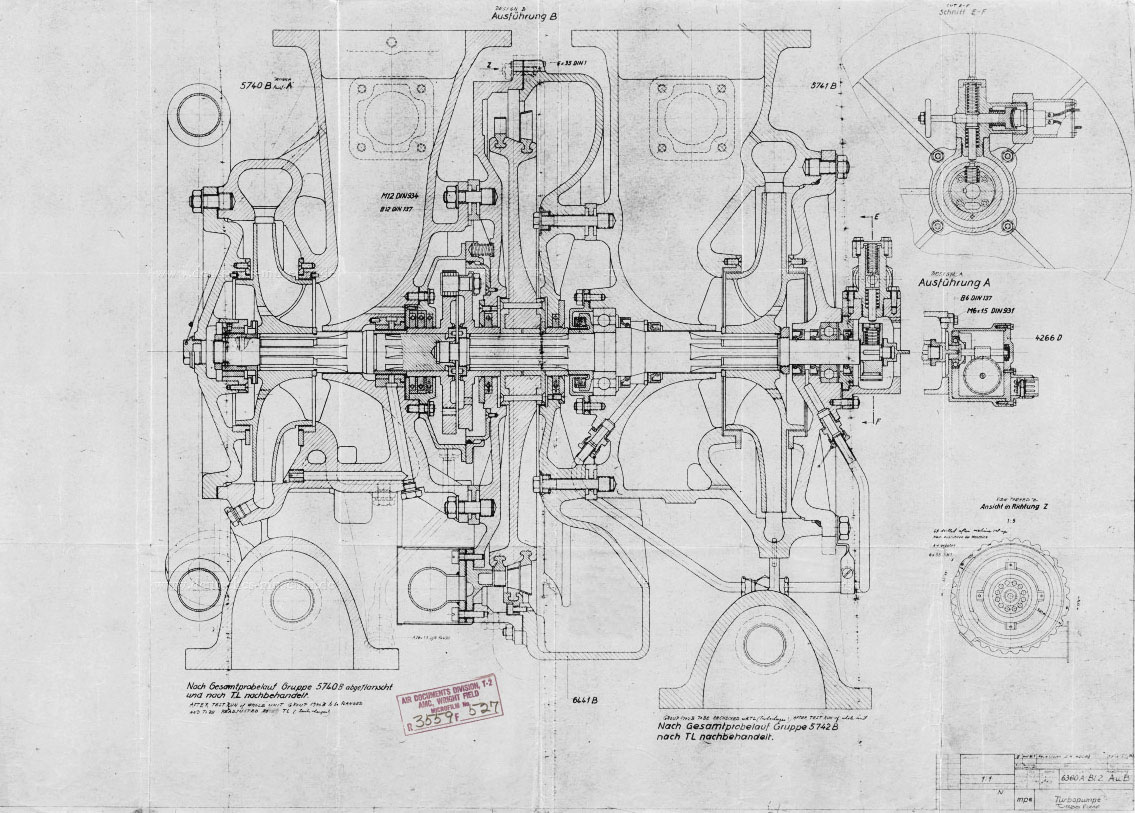
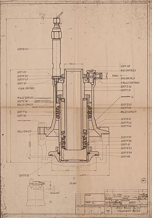
Diagrams and drawings featuring any one of the 18 individual burner cups usually show each cup as being identical to one another regardless of their position on the injector head. That is, whether they are one of the twelve burner cups situated on the outer ring (Ring I) or the six inner ring (Ring II) cups is not noted as significant. But this is incorrect as the two rings exhibit different fuel injector insert permutations, even though at first glance they look similar. Both types use a mixture of high volume 3304D and lower volume 3303D and 3305D injector inserts.

In the case of the lowermost insert echelon E used in the inner circle of burner cups (Ring II), all sixteen are of the high volume 3304D type. Whereas the lowest echelon E ring of inserts in the twelve outer injector cups (Ring I) are split ten 3304D types and six lower volume 3303D injectors (see B-Stoff chart 0-4554 D in the image gallery at the bottom of this page). The low volume 3305D type fuel injectors in the burner cups of Ring I are positioned to be adjacent to the outside wall of the injector space. This positioning was done to concentrate fuel to the central axis of the combustion chamber. So not only were the injector cups angled on the injector head to focus the outlet nebula into the centre of the combustion cavity, but the outer circle of burner cups also have an asymmetrical insert pattern to maximise mixed fuel flow to the centre of the combustion chamber. We are uncertain as to when this latter injector permutation began as it appears in the drawing record too sporadically to offer a reliable start date. We would be interested to hear from readers who have accurate information on when this refinement was first proposed.
The image gallery below has the above pictures in higher resolution, some with additional text, as well as additional pictures not included in the article.