Gallery of images showing a 3D CAD model of V2 rocket turbo-pump transcribed from original HAP drawings by Ray Matter
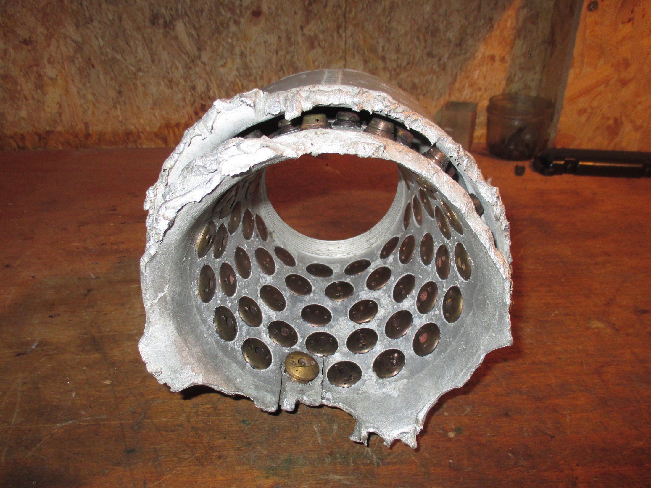
Relic of prototype A4 25-ton 1940/41 aluminium injector head basket (or pre-chamber) showing 68 copper alloy inserts in 5 rows. The standard configuration would later become 44 inserts in 3 rows 25 2mm diameter drilled holes in two rows situated at row 3 and 4 (counting from nearest the camera). Photo courtesy Host Beck Collection
| Album | V2 rocket fuel injector inserts |
| Categories | Anatomy of the V2, Combustion |
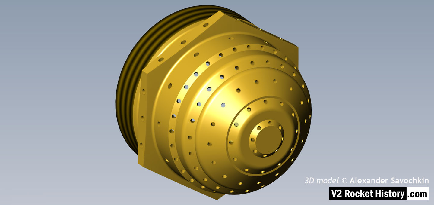
Brass liquid oxygen (LOX) spray nozzle.Note: the thread is shown in simplified graphic form. 3D model by Alexander Savochkin
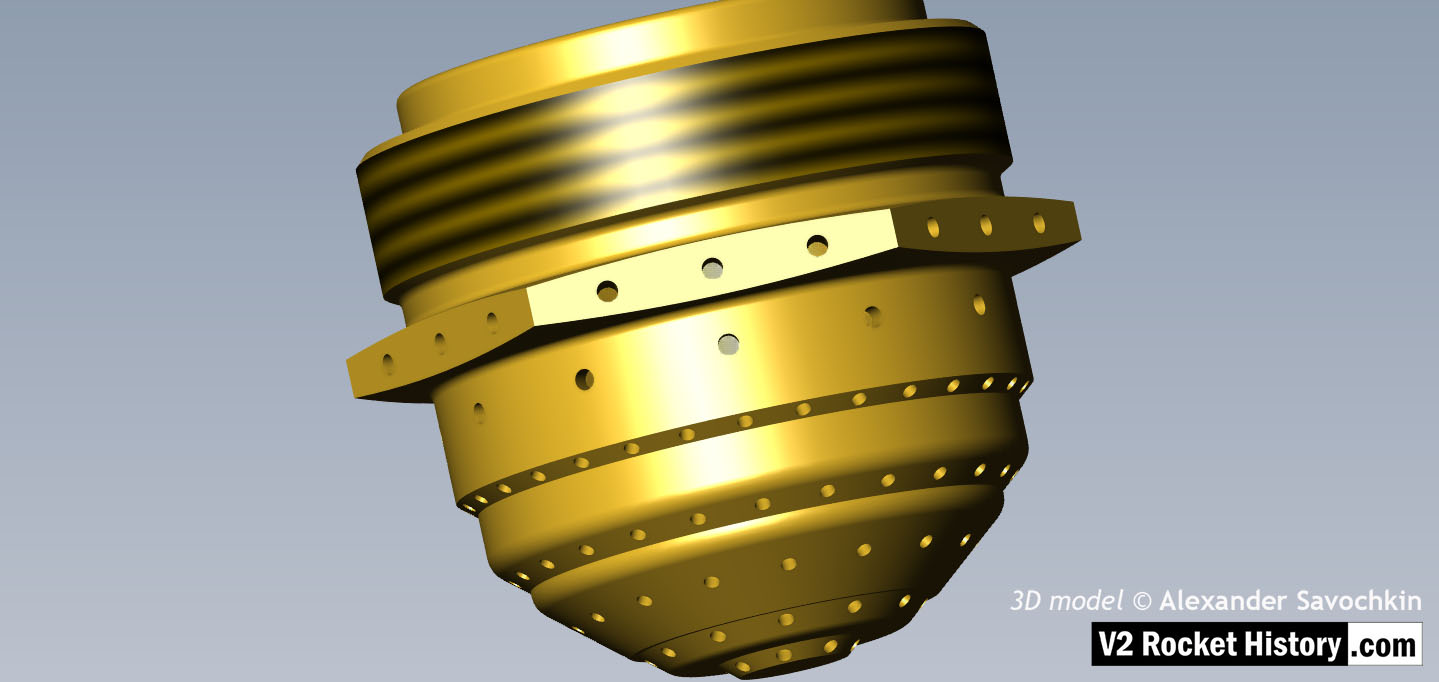
Brass liquid oxygen (LOX) spray nozzle. Note: the thread is shown in simplified form. 3D model by Alexander Savochkin
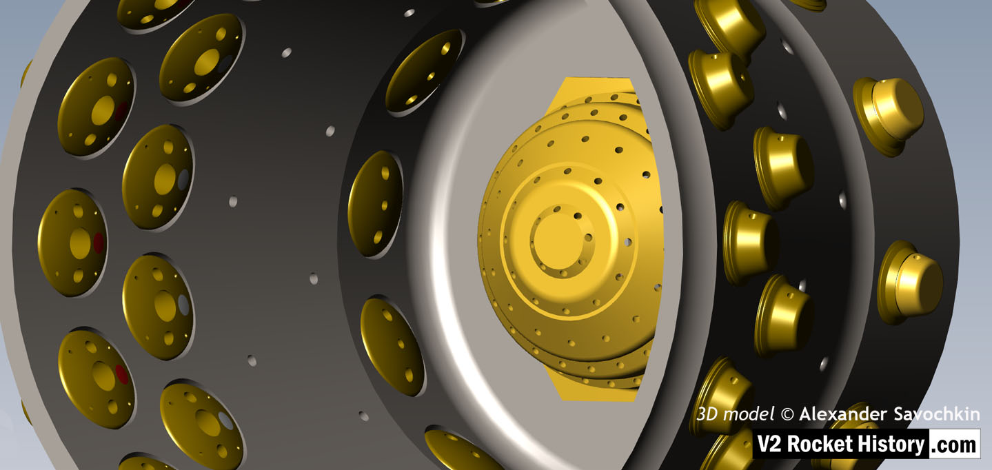
One of the 18 liquid propellant (LOX and fuel) diffuser cups, showing three rows or echelons (A,D,& E) of brass injector inserts as well as two rows of drilled fuel feed holes. The LOX spray head is shown in the centre. 3D model by Alexander Savochkin
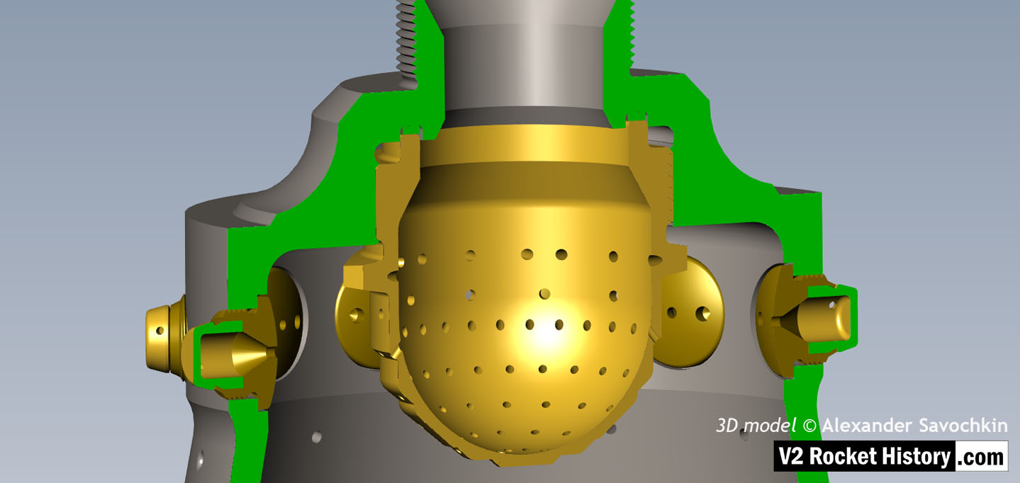
Cutaway showing echelon A with 2-part 2131E fuel injector inserts at the top of a propellant diffuser cup. Note the close proximity of the injector inserts to the simple 'watering can' type LOX spray head. One row of drilled fuel feed holes can be seen below the inserts. 3D model by Alexander Savochkin
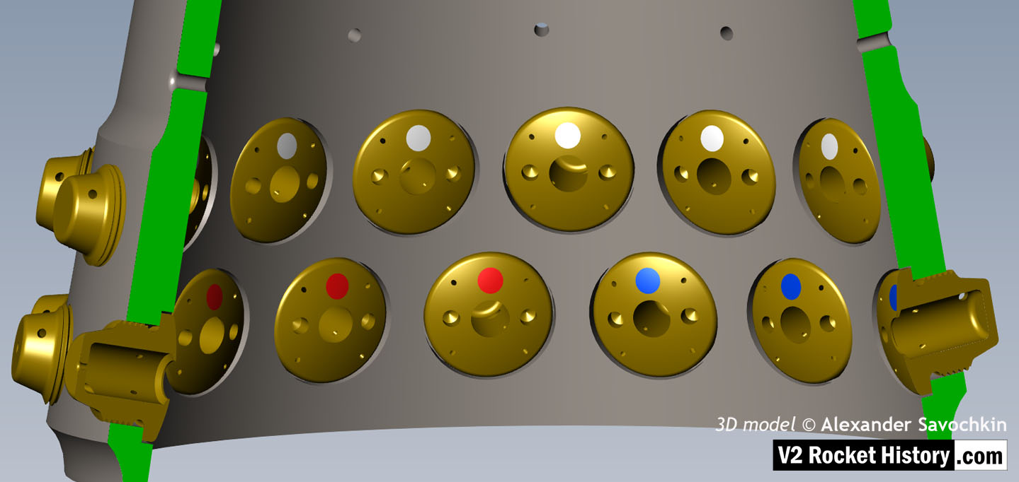
This images shows a cutaway of a burner cup from outer Ring I of the injector head and shows injector insert eschelon D, & E as well as one row of drilled feed holes. Three fuel injector insert types can be seen: Top D, = 3303D (white), lower E, = 3304D (red), and E, = 3305D (blue). 3D model by Alexander Savochkin
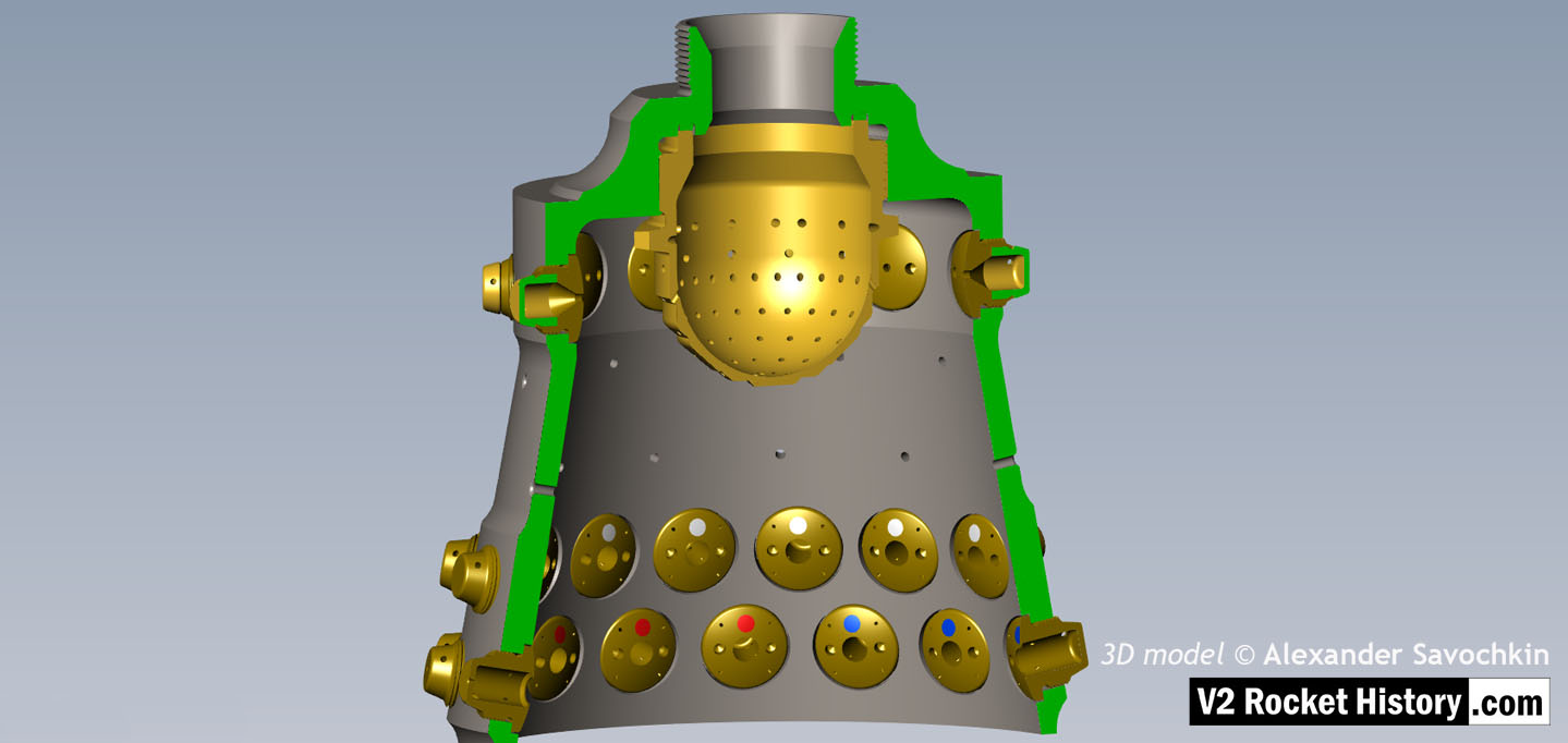
This images shows a burner cup from outer Ring I of the injector head and the cutaway shows injector insert eschelon A,D, & E as well as two rows of drilled feed holes. Four fuel injector insert types can be seen: Top, A = 2131E, lower D, = 3303D (white), lowest E, = 3304D (red), and E, = 3305D (blue). 3D model by Alexander Savochkin
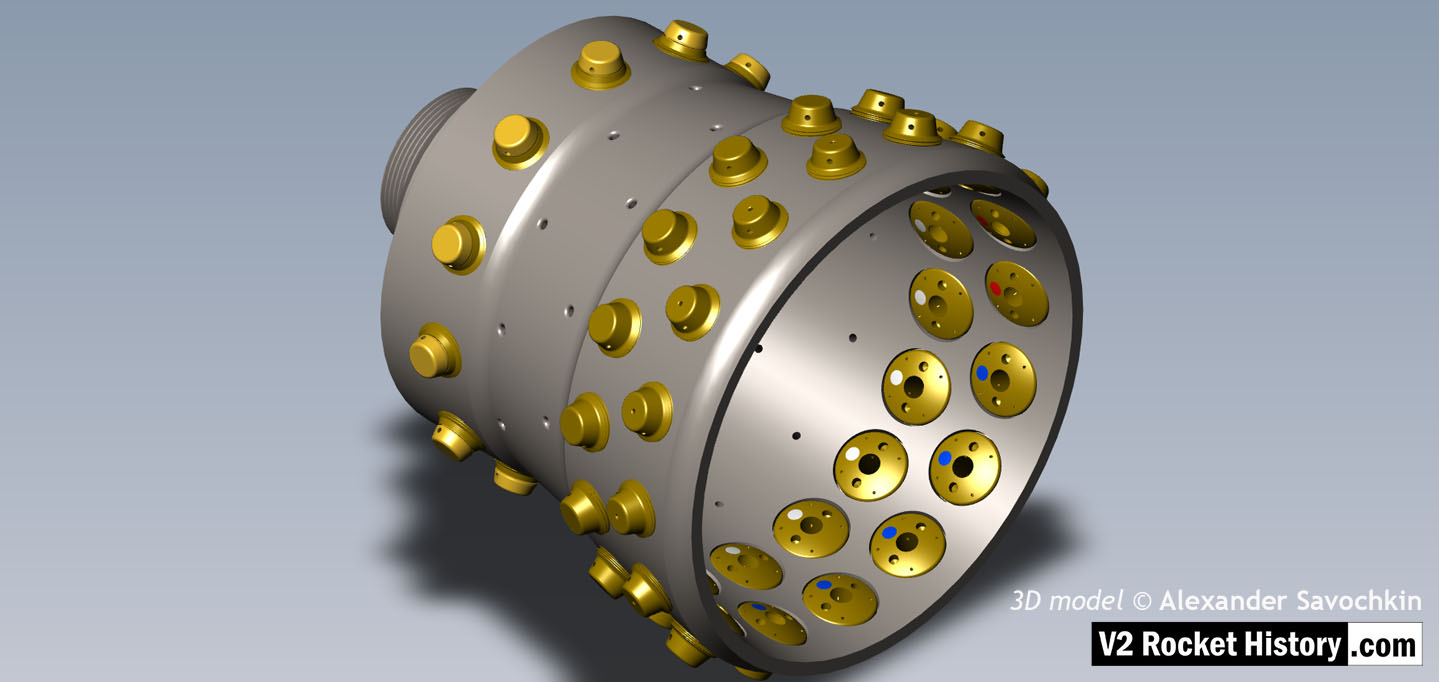
General view of the propellant diffuser cup inner core. The swirl caps of fuel injector inserts in positions A,D,& E can be seen clearly on the outside of the core as well as the central holes in the 3304D (red) inserts.The two rows of drilled fuel feed holes are also well shown. 3D model by Alexander Savochkin
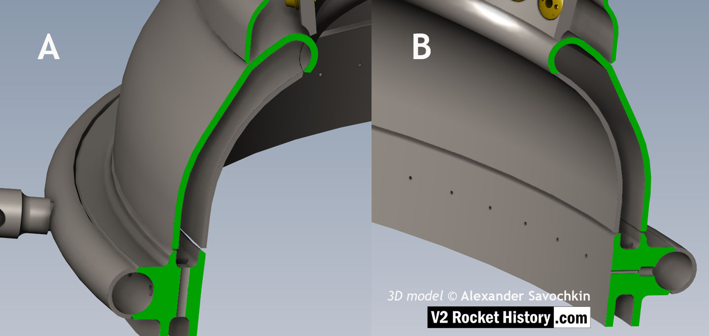
Close-up detail showing independent pathway for fuel passing into injector head and fuel passed down from the head to be used for veil cooling system. Fig. A shows vertical passages for overall fuel feed to the head and Fig.B shows horizontal pathway for veil coolant fed from the head via the veil coolant distributor ring or manifold. 3D model by Alexander Savochkin
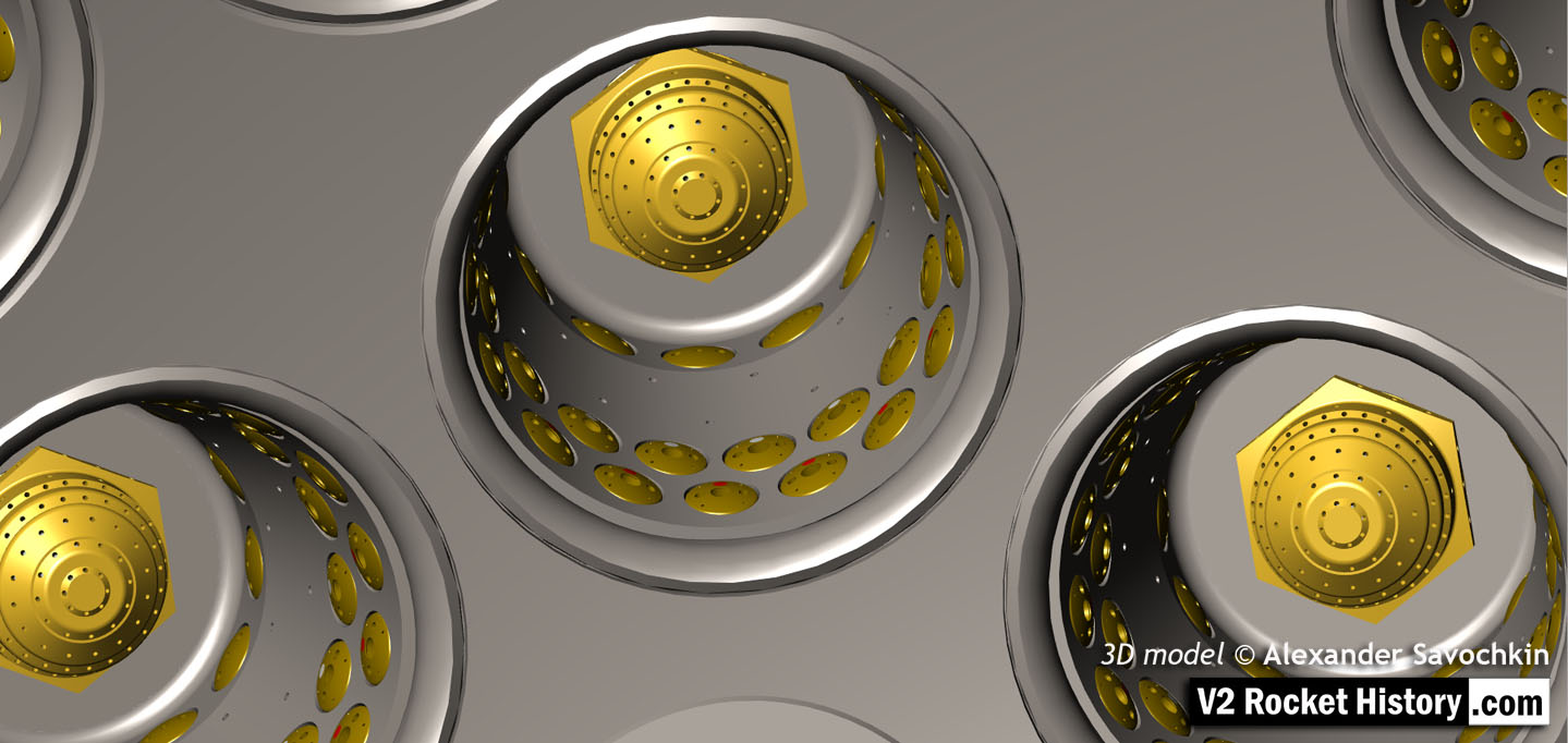
Underside view of injector head showing liquid propellant (LOX and fuel) diffuser cups, (see other images for insert and position nomenclature). Of note in this image are the pointing angles of the cups, positioned on a parabolic section to focus the propellant nebular stream into the central axis of the combustion space. Also of note are the large areas between each cup NOT employed in the injection process - initiating 'clumpy' and uneven propellant mixing initially below the injector face but also carried forward into the combustion space. The LOX spray head is shown in the centre of each cup. 3D model by Alexander Savochkin
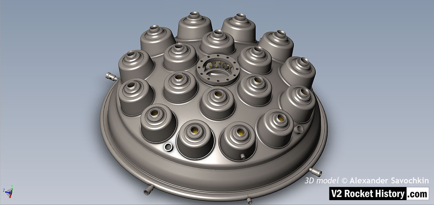
Inverted view of injector head showing liquid propellant (LOX and fuel) diffuser cups, (see other images for insert and position nomenclature). Of note in this image are the pointing angles of the cups, positioned on a parabolic section to focus the propellant nebular stream into the central axis of the combustion space. Also of note are the large areas between each cup NOT employed in the injection process leading to structured propellant mixing as opposed to even homogeneous mixing. The four veil cooling inlet connectors are well shown. 3D model by Alexander Savochkin
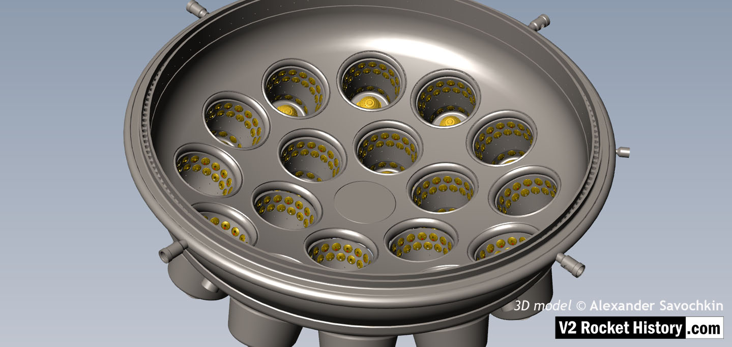
View of injector head showing 18 liquid propellant (LOX and fuel) diffuser cups and head fuel valve seating ring at centre, (see other images for insert and position nomenclature). Visible immediately below the valve seat are the large connecting holes that allow fuel to flow from the inlet manifold and cooling jacket to the injector space (some brass injector inserts can be seen through the holes) after the head fuel valve is released to be opened by the turbo-pump supply pressure. The four veil cooling inlet connectors are well shown as are two of the outlet connection holes immediately above them. 3D model by Alexander Savochkin
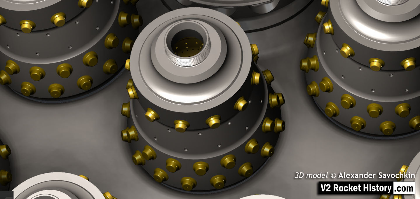
View of the top of the injector head, with outer cups and pressed steel capping piece removed, showing, propellant diffuser inner cores with injector inserts and LOX supply pipe connection thread. The LOX spray head can be seen inside the LOX pipe connector. The swirl caps of fuel injector inserts in positions A,D,& E can be seen clearly on the outside of the cores and the two rows of drilled fuel feed holes are also well shown. 3D model by Alexander Savochkin
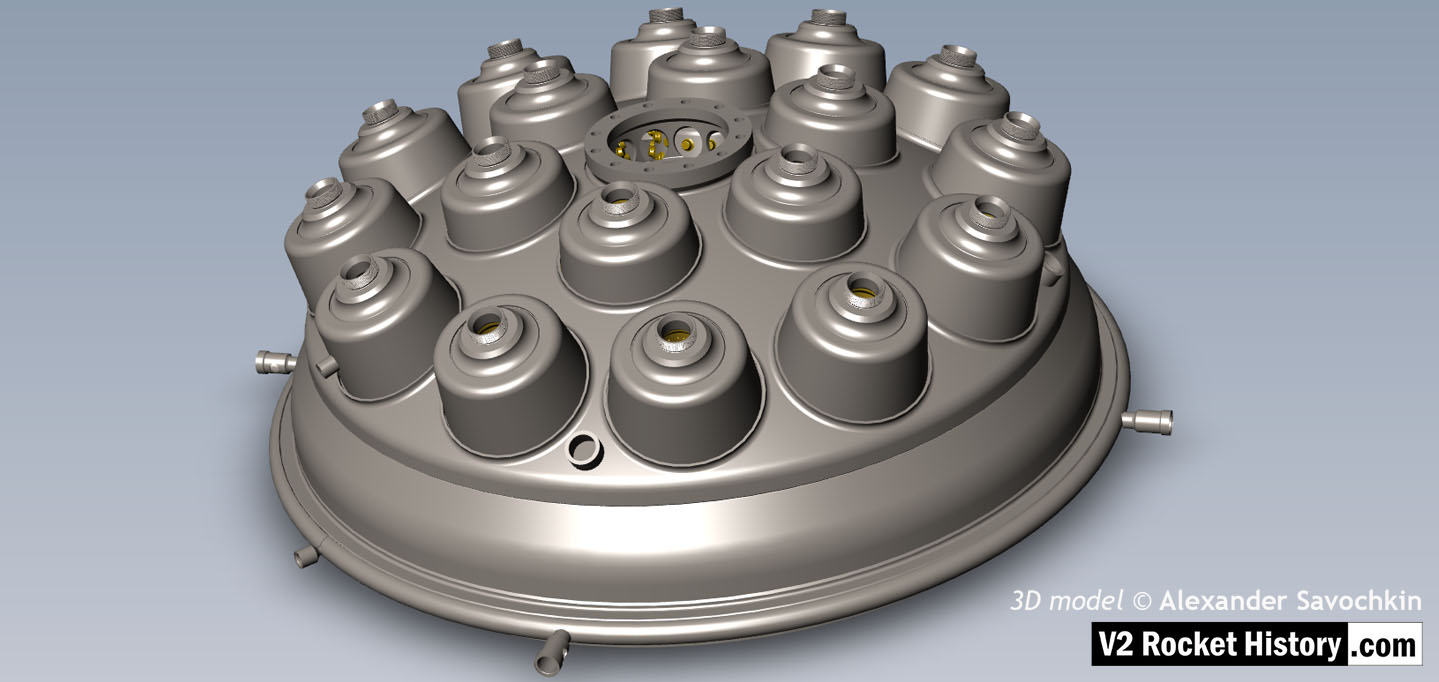
Another view of injector head showing liquid propellant (LOX and fuel) diffuser cups and head fuel valve seating ring at centre, (see other images for insert and position nomenclature). Visible immediately below the valve seat are the large connecting holes that allow fuel to flow from the inlet manifold and cooling jacket to the injector space (some brass injector inserts can be seen through the holes) after the head fuel valve is released to be opened by the turbo-pump supply pressure. The four veil cooling inlet connectors are well shown as are two of the outlet connection holes immediately above them. 3D model by Alexander Savochkin
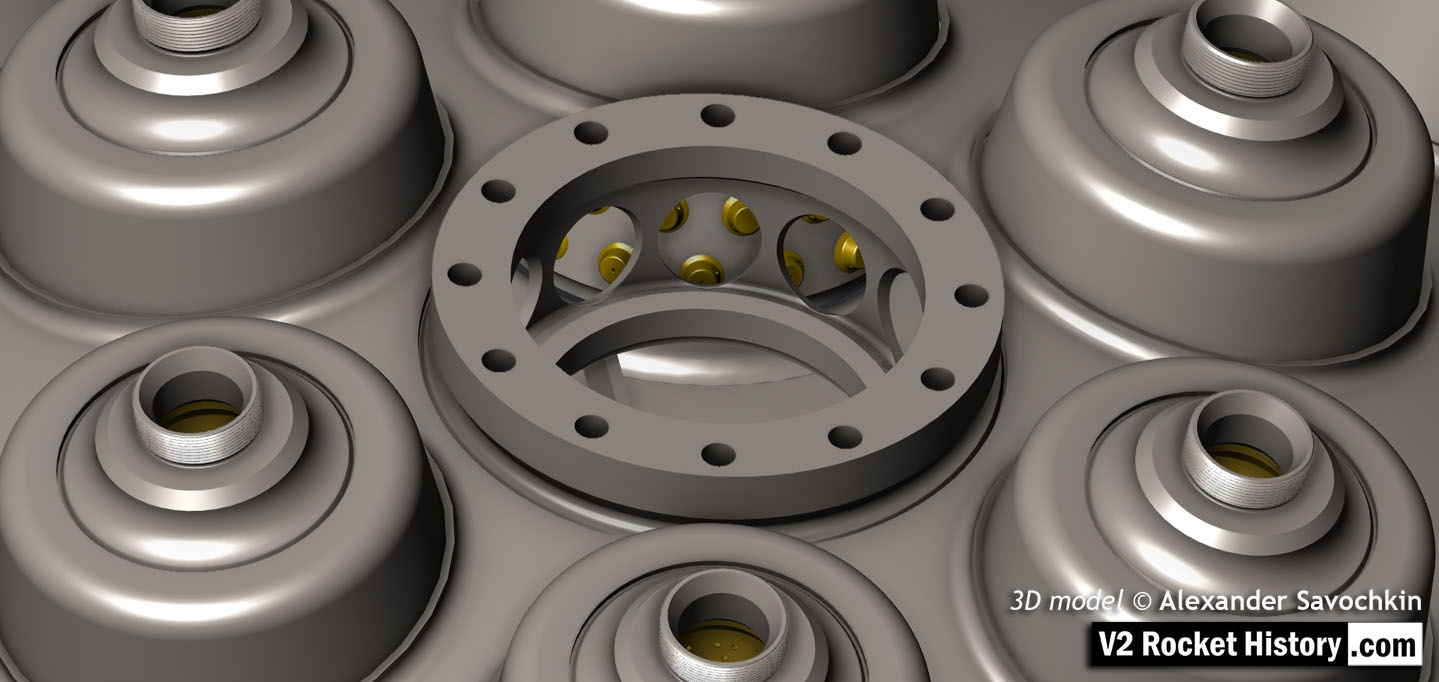
A close-up view of the head fuel valve mounting flange (showing 12 fastener holes). Visible immediately below the top flange are the large connecting holes that allow fuel to flow from the inlet manifold and cooling jacket to the injector space (some brass injector inserts can be seen through the holes) after the head fuel valve is released to be opened by the turbo-pump supply pressure.
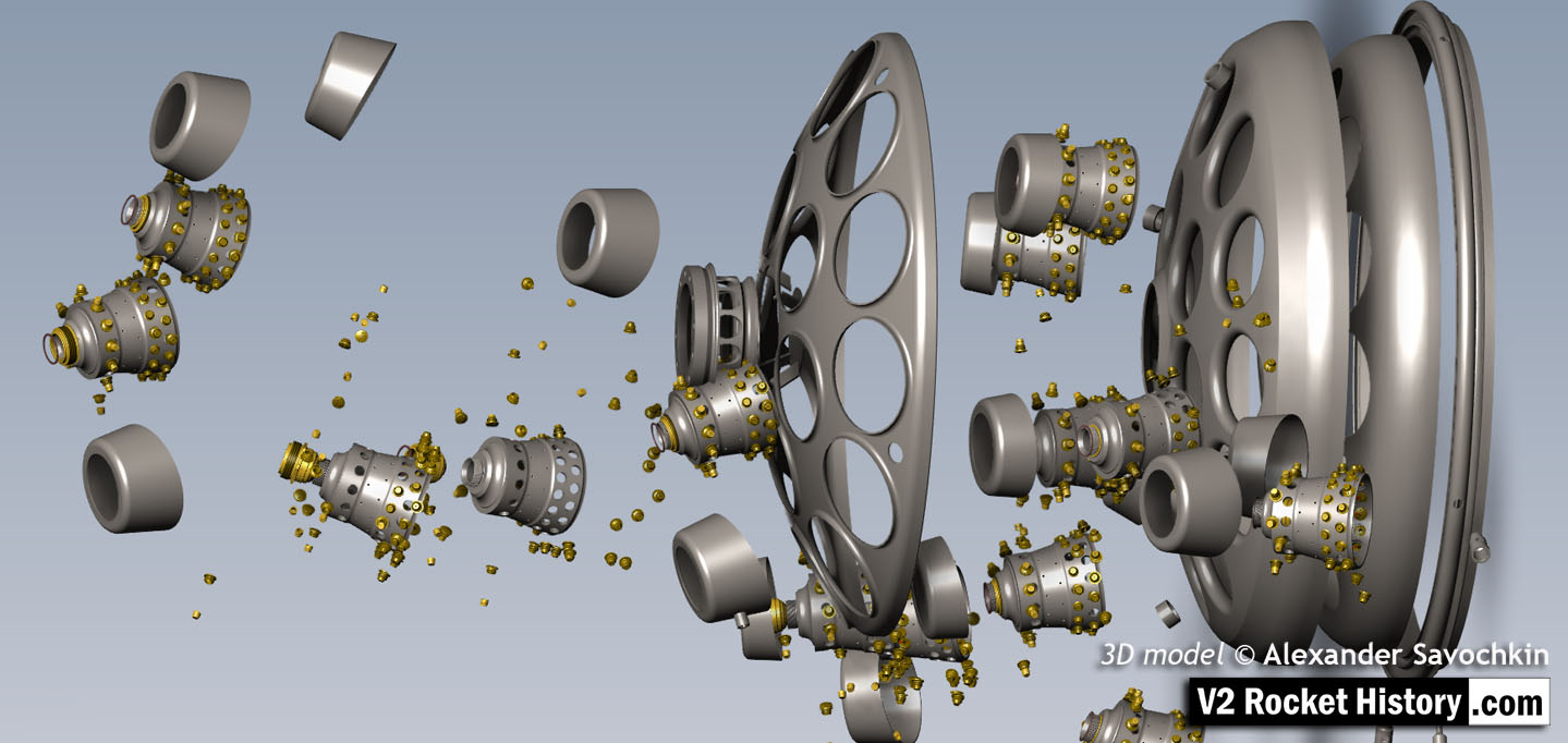
Exploded view showing some of the 1100 parts required for the complicated 18-pot injector head of the V2 25-ton thrust rocket engine. 3D model by Alexander Savochkin
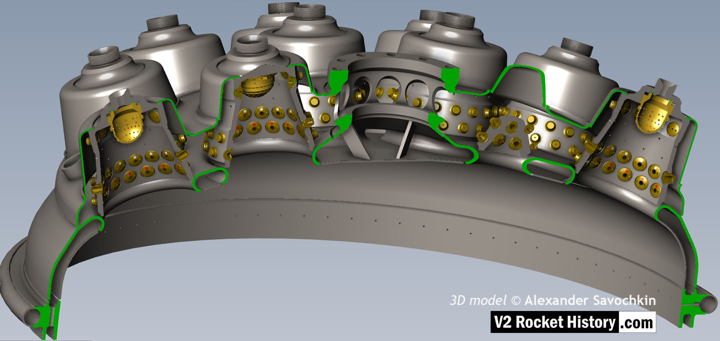
Here the 18-pot head model has been cutaway to show the fuel cooling and fuel delivery spaces. the cooling jacket layer can be seen in the lowermost area of the head - below the centrally positioned fuel valve seat, between each cup at the lowest point, and ruining down toward the first set of veil cooling pores and the topmost coolant distributor ring. Note that the veil cooling system does not communicate with the regenerative cooling jacket and has its own feed pipes drawing fuel from the head injector space and not the cooling space. Visible immediately above the valve seat are the large connecting holes that allow fuel to flow from the inlet manifold and cooling jacket to the injector space after the head fuel valve is released to be opened by the turbo-pump supply pressure. 3D model by Alexander Savochkin
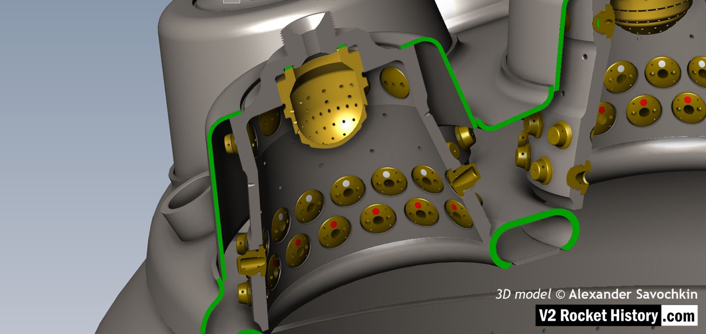
Liquid propellent (LOX and fuel) diffuser cup, showing three rings or echelons (A,D,& E) of brass injector inserts as well as two rows of drilled fuel feed holes. The LOX spray head is shown in the centre. Note the simple 'shower head or watering can' design of the LOX diffuser. A sealing washer can be seen fitted between the LOX diffuser and the steel cup. 3D model by Alexander Savochkin
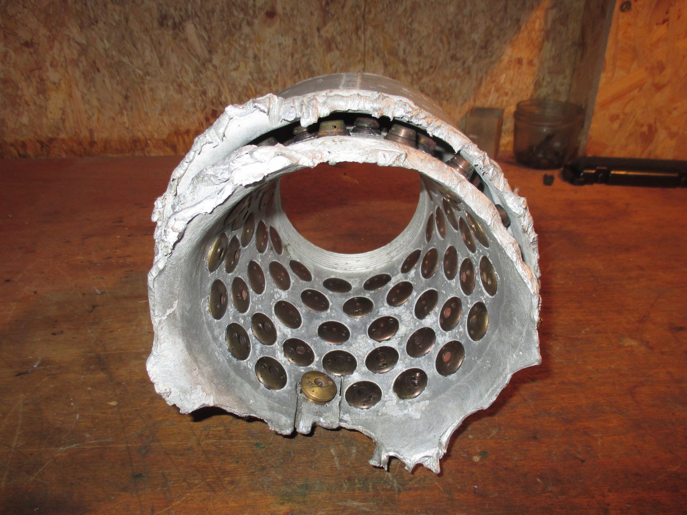
Relic of prototype A4 25-ton 1940/41 aluminium injector head basket (or pre-chamber) showing 68 copper alloy inserts in 5 rows. The standard configuration would later become 44 inserts in 3 rows 25 2mm diameter drilled holes in two rows situated at row 3 and 4 (counting from nearest the camera). Photo courtesy Host Beck Collection


