
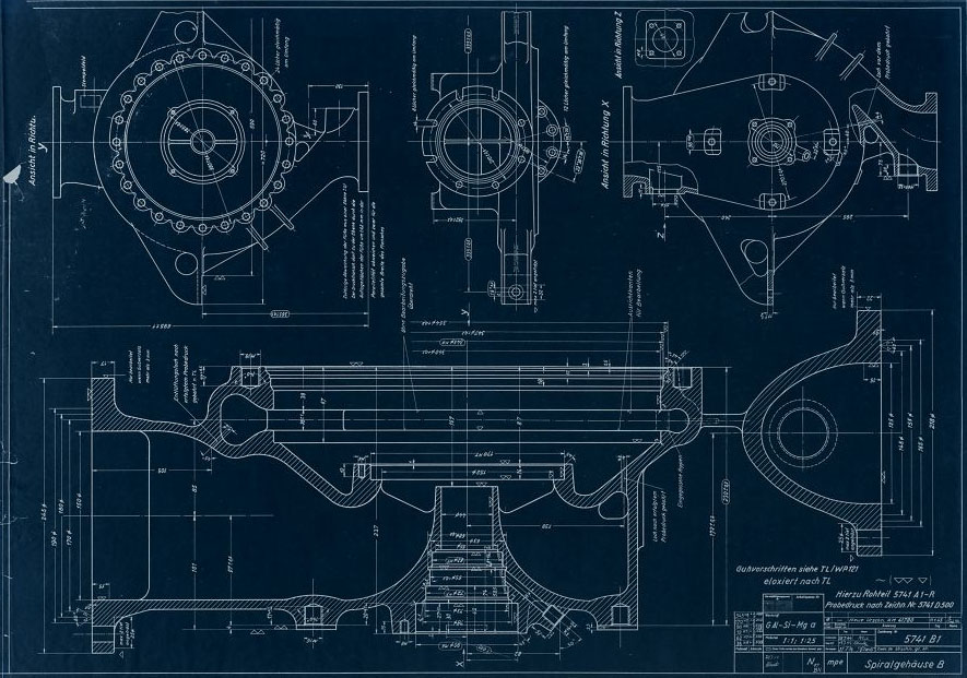
Drawing 5741 B1 mpe - Fuel (B) Pump Spiral-housing with dimensions. Drawing origin 18 July 1944, revised to new drawing (AM41780) 11 Jan 1945. (Digipeer.de image)
| Album | V2 rocket turbo-pump |
| Category | Turbo-pump |
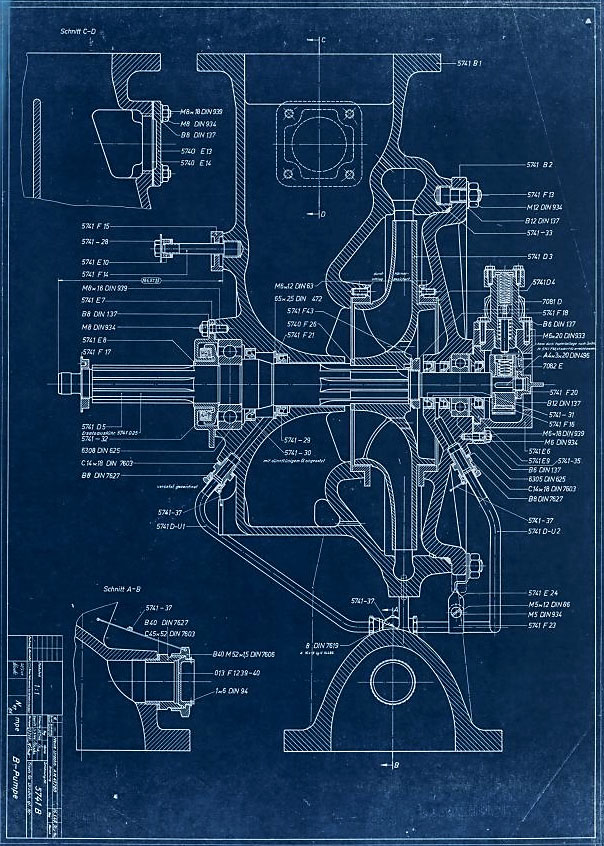
Drawing 5741 B mpe - Fuel (B) pump assembly showing part/drawing numbers. Drawing originates 20 July 1944 and revised with new number (AM41780) 16 Jan 1945. (Digipeer.de image)
| Album | V2 rocket turbo-pump |
| Category | Turbo-pump |
Animation highlighting just one of many revisions to the turbo-pump that occurred at an accelerating rate between August 1943 and late 1944 as the missile moved from development to full production, and finally use in combat. (Digipeer.de images: animation RJD)
| Album | V2 rocket turbo-pump |
| Category | Turbo-pump |
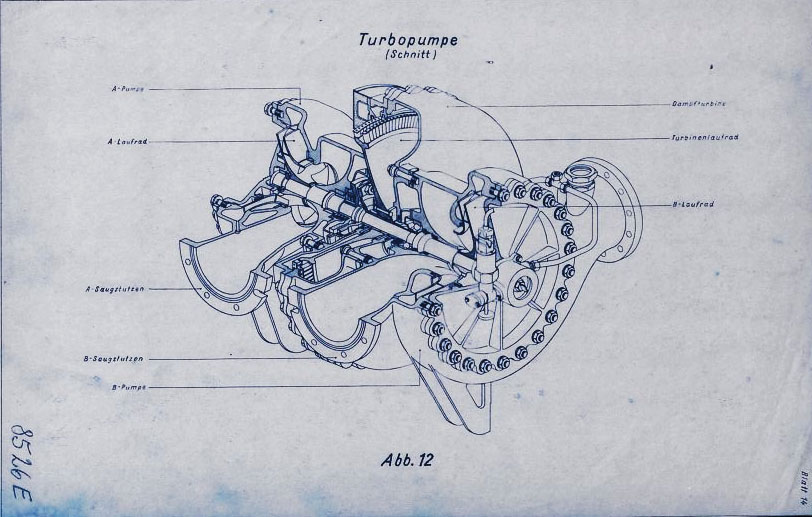
Drawing 8526 E mpe 1944: Turbo-pump training presentation image showing cutaway. (Digipeer.de image)
| Album | V2 rocket turbo-pump |
| Category | Turbo-pump |
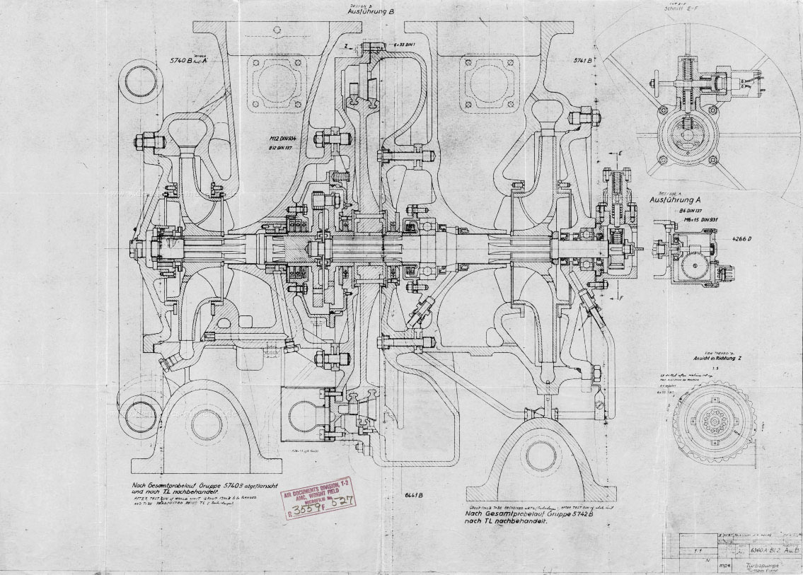
Drawing 6380 A - Turbo-pump Assembly 08 Aug 1944. (Digipeer.de image)
| Album | V2 rocket turbo-pump |
| Category | Turbo-pump |
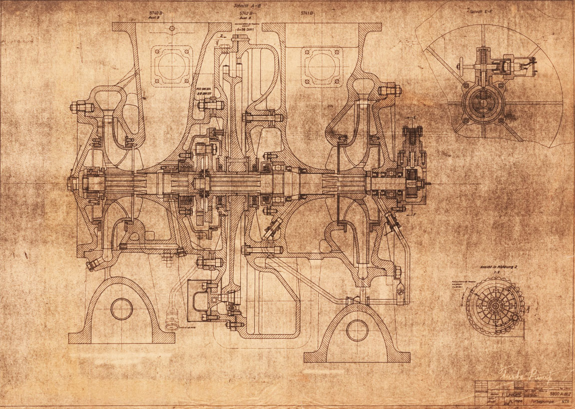
Drawing 5800 A - Turbo-pump Assembly 1 March 1944. (Digipeer.de image)
| Album | V2 rocket turbo-pump |
| Category | Turbo-pump |
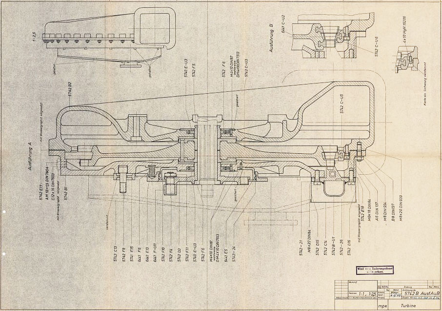
Drawing 5742 B - Steam Tubine Assembly showing part/drawing numbers. (Digipeer.de image)
| Album | V2 rocket turbo-pump |
| Category | Turbo-pump |
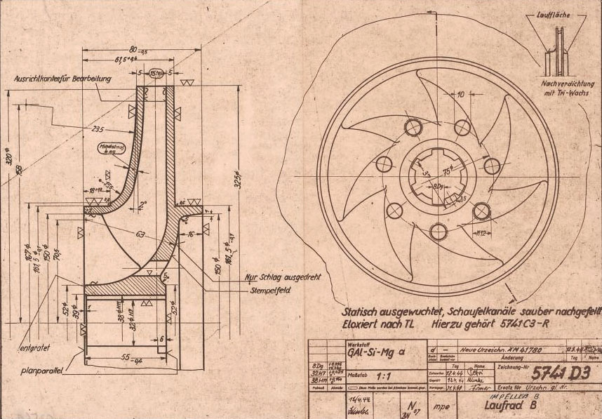
Drawing Number: 5741 D3 showing B (fuel) pump centrifugal impeller mpe drawing dated April 1944. mpe original drawing (Digipeer.de image)
| Album | V2 rocket turbo-pump |
| Category | Turbo-pump |
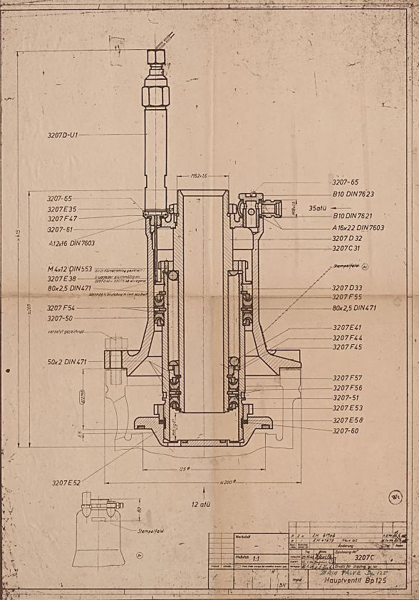
Original mpe 1944 drawing number 3207 C of main fuel valave. (mpe = Heimat-Artillerie-Park Karlshagen, Werk Nord Peenemünde).
| Album | Valves |
| Category | Propellant flow |

The injector head section of the 4B 1000kg thrust rocket engine is a precursor to the injector pot or 'pre-chamber' design used later for each of the 18-pots of the 25-ton V2 rocket engine. Most of the essential ingredients are shown in this drawing from 1940. Drawing no 1848E Deutsches Museum München online archive ref FA 014/12829
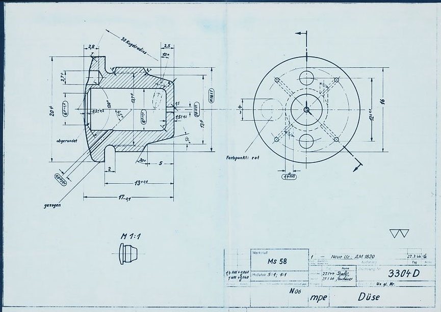
HAP11 drawing of standard 3304D fuel injector screw insert. showing details of primary swirl cavity and orrifice and all additional apertures including the four small cooling pores. HAP11 (Heimat-Artillerie-Park 11, AKA armament code: mpe), drawing number 4554D, Deutsches Museum München

HVP drawing no 1203D showing burner cup 'diffuser system' disposition for 19-pot head (at this stage the 25 ton thrust injector head had nineteen so called 'pre-chambers' or pots as no central fuel valve was present). HVP drawing dated 1939.
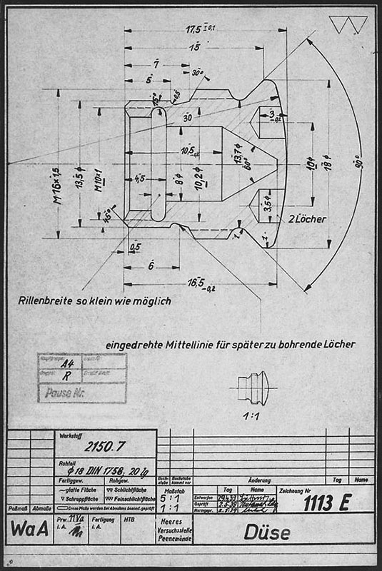
Drawing from the Army Experimental Station Peenemünde dated 1939. The specification describes an insert template that could be used for a range of outlet and inlet orifice sizes. The German text beginning (eingedrehte ...) translates as 'Center-line of screw used for holes to be drilled later', and the hole dimensions are not specified on this document. HVP drawing number 1113 E, Deutsches Museum München
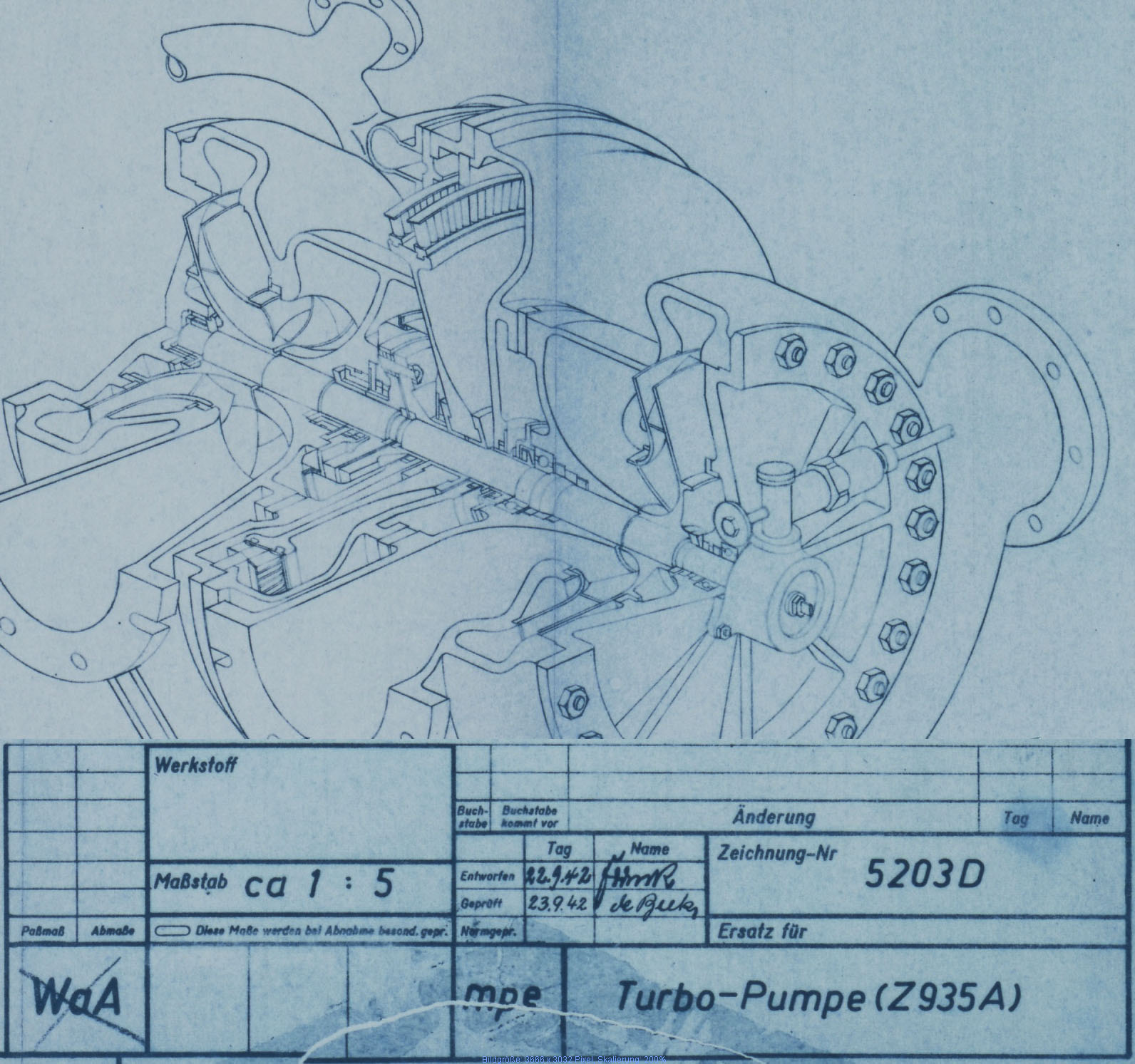
Sectioned general assembly view of the V2 turbo-pump (TP) dated September 1942. This image has been edited to show TP and document data closer together than the original.
Specification for fuel injector inserts showing orifice size, type, and A to E echelon position. Peenemünde document dated 30th October 1943. Of note on this document is the combination of high and low volume injector inserts (3304D and 3305D) in the echelon E position of the 12 cups comprising outer ring I. It shows that each cup or pot on this outer ring had 16 inserts at the lowermost position E with 12 of the inserts with three inlet apertures (3305D) and 6 with only two inlet apertures (3304D being lower flow volume) positioned in the segment covering 165 degrees and closest to the outside edge of the head. HAP11 (Heimat-Artillerie-Park 11, AKA armament code: mpe), drawing number 4554D, Deutsches Museum München
